Water Proof Back Pack Blaster
GFI 10 - 6W
Concept
A few weeks ago, we recieved a request (or rather a challenge) from a friend, to see if we could build a back pack boom box similar to the earilier model. It didn't have to be small or light, unlike the latest model (the Run Pack) weight was not an issue, but it had to be loud, and WATERPROOF. A feat such as this had never been attempted before by GFI. The design process was started by considering different methods of waterproofing the amplifier boards. I had aquiered a second hand pair of speakers for free a long time ago and this woud be the perfect application for these. It was finally detirmined that the best method of waterproofing the critical amplifier boards was to enclose them in a millitary grade ammunitions box. These boxes are waterproof and are made of heavy steel. They are designed to withstand war, so why shoudn't they work for a Ghetto Blaster. Waterproofing the entry for the wires into the ammo box would be considered later.
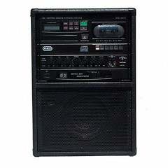
The Amplifier boards were harvested from an old Karaoke Machine. They are used for many applications at GFI because they are easy to modify, easy to mount, and quite abundant at the local transfer station.

The Base for the entire thing would be a Gerry Baby carrier. I use just the frame for the backpack. The rest is useless. It is used for the same reasons as the Karaoke machines.
Materials
- Karaoke Machine
- Ammo Box
- Baby carrier
- Toggle Switch
- Wires
- 1/2" plywood for the rear gasket
- 3/8" plywood for the face plate
- Red Oak for the toggle protector
- Wind Surfer Sail Material (or othe waterproof plastic) for the speaker coverings
- Silicon Caulk to waterproof everything
- 1" Maple for the stress releiving Gromit
- Various assorted sized of Nylon ripstop straps for all sorts of connections
- 1/8" Stereo Jack and cord (I harvested one off of a pair of computer speakers)
- Shrink wrap cable protector
- Wind on cable protection
- Black Paint
- Semi-gloss poly urethane
- Silver Sharpie (for all labels)
- Batteries
- 1/4" Aspen for the new battery box lid
- Velcro for the battery box lid
- Various and Sundry Screws
- Foam for amp board cushioning
- Speaker Covers (from pioneer car speakers found at the transfer station)
Construction
1 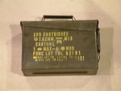
This is the Ammo Box that was purchased at the army navy store. It was one of a few items purchased, and was the most expensive part of the pack, costing $8.00. Inside this will rest the two amplifier circuit boards. At the army navy store I made sure that there were no holes or rust in the box and that the gasket on the top was still good.
2 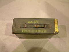
This is the top view of the ammo box lid. Because of the wide swing on the lid, a method for removal of the ammo box off of the frame of the pack would be the most efficien way to access the interior of the Ammo Box.
3 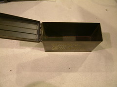
The inner gasket on the ammo box is crucial. It must still be good because it has to keep the water out and the electronics dry.
4 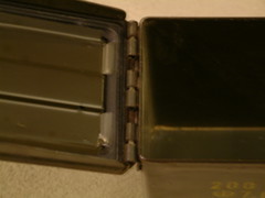
Because the hinge on the top of the Ammo Box is designed to be taken apart (You can completly remove the lid from the rest of the box) extra wire will be left on the inside of the box. That way, when the amplifier needs to be inspected, the pack can be lay down and the box can be removed and set upright for diagnostic work.
5 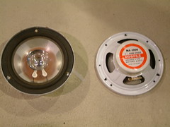
I got the water proof speakers from a teacher I had many years ago. They a still perfectly fine and will be finally put to a good use here.
6 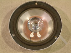
The Front of the speaker is left open. The cone, instead of being paper, is plastic, and it is completley waterproof from front to back
7 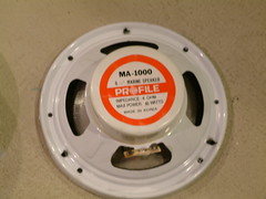
The back of the speaker is also sealed and coated with plastic. All of the wiring and the backs of the speakes will be waterproofed later on but if water ever did get back there, the speakers will be safe no matter what.
8 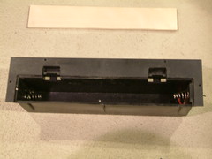
The Battery box (holds 8 "D" Cell batteries or 12 volts) was taken from the Karaoke Machine and was cut off of the part that also held the cord. Therefore, the old cover will not work. A new one is made out of 1/4" aspen to fill the hole. Individual batteries are waterproof and will therefore be safe from water, the battery box is also higher, being held between the two uppermost supports on the baby carrier in the same fashion as the other large backpack. The higher they are on the pack, the less affected by the water.
9 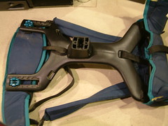 10
10
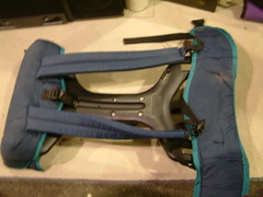
The base for the Back Pack is a Gerry Baby Carrier. The carrier has a hollow plastic body with three large posts sticking out of the back. The lower middle has screw hols but will be cut down so as to achieve a better angle. The upper two posts were damaged in removal. They were replaced with wooden blocks that will offer a wider range of adjustability and will work better.
11 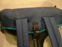
The upper shoulder straps are good enough to use, but the straps lack a sternum strap (that will pull the upper end of the back pack closer to he back of the wearer's body and ake it more comfortable) This feature was lacking on the last two back packs, but is common on hiking packs.
12
The lower belt strap is fine and will not be modified, but the clip on the belt was broken, and will be replaced.
13 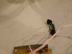
The Power indication LED is not needed (and will not be seen) in the Ammo Box, so its wiring will be lengthened and the LED will be mounted in the center of the Face plate.
14 
The Karaoke Machine originally ran off of both AC and DC power and had an AC to DC converter, and a switch, to choose which power source to use. Removing the AC DC converter renders the switch obselete, it would be removed completely, but the power line runs through it. Instead of being removed, it will be permanently stuck in the DC mode.
15 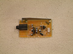
It was quickly realized that the Amplifier cicit boards were too long to fit completly into the ammo box. After much testing, some parts of the board were demmed unessescary. This is one of the Microphine imputs. This part is not needed in the final product. This is not the back pack's purpose, so the jack is expendable.
16 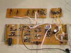
This is a view of all of the pieces of the Amplifier board together after they have been cut. The two largest pieces will be used now that they fit into the ammo box. The smaller pieces will be thrown out.
17 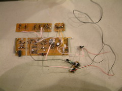
The very small boards in the lower right of this picture are the input and output boards. The output will also be thrown away becaue any more hoes in the ammo box would comprimise its water tight abilities.
18 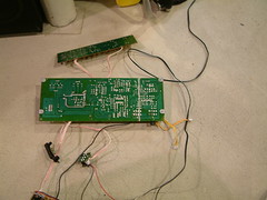
These are the boards prior to diceing them with a dremel cut off wheel.
19 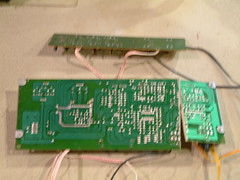
The bigger board was the main amplifier board the portion that was removed was the microphone jack, it was not nessescary and was removed. The smaller board near the top of the picture was a five band graphic equalizer, volume control, and microphone volume controller and mic. echo control. The last two wern't needed without microphone jacks so were they were cut off. All of the controls will be inaccesable inside the ammo box. This is done to ensure that there is only one hole in the box. The only control is just on or off. Volume will be controlled by the Handheld MP3/Audio player.
20 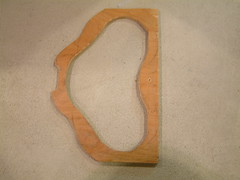 21
21 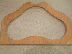
The Speakers, wires, toggle, and LED will all be waterproofed with wind surf sail material (which is strong, clear, and waterproof). The sail material will be held onto the rest of the face plate by caulking the area and tightening it to the face plate with a large gasket made out od 1/2" plywood that will be screwed onto the faceplate.
22 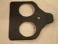
The Faceplate is made out of 3/8" plywood and now has the holes cut in it to recieve the speakers. When the pack is finished, the speakers will be held in with screws. In between the back lip of the speaker and the Front of the faceplate, caulk will be added to ensure that no water will enter the speaker cavity and sit there.
23 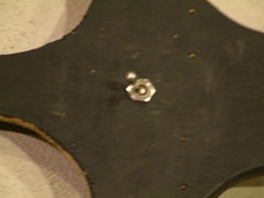
The hole for the Toggle Switch for power is drilled. It is located between the speakers.
24 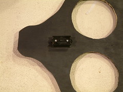
The Toggle should be water proof. The only worrisome thing is the possible corrosion of the toggle. If this happens a new toggle will be added.
25 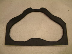
The Gasket Painted with matte black acrylic paint.
26 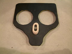
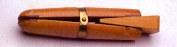
The toggle switch will be vulnerable if the wearer was to fall over, or roll on their back. The toggle could turn from off to on or from on to off, or it could break off. To protect from this. I designed a toggle protector modeled off of a power tool sitch protector (it is easy to turn off, but you have to try to turn it on).
27 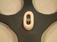
The Protector is made from 1/2" Red Oak and is an eliptical shape. It is very contured, nearly half a circle.
28 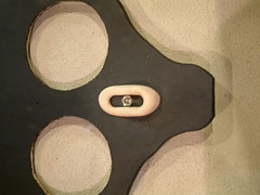
The upper half of the protector is sanded away, this ensures that it is easy to turn off (down), but not on (up) accidentally. This can be seen better in picture 31.
29 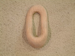
The final design for th protector before paint.
30 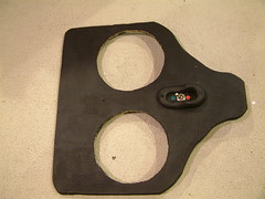
After painting the safety switch cover black, a simple red dot for off and a green dot for on are added.
31 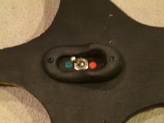
A close up of the safety cover better shows the contour that allows best use of the switch.
32 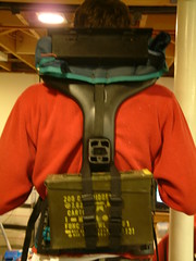
The Back pack as it looks now in the process. The battery box can be seen in its final destination. It will be covered by the faceplate.
33 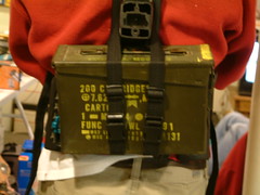
The harness for attaching the ammo box to the backpack is made out of nylon straps.
34 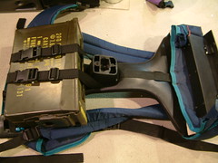
The Harness works exceptionally well and holds the ammo box very tightly, however, to allow for greater security more lateral support will be added in the form of a strap that runs transversly across the ammo box.
35 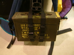
The new strap will run from side to side on the box and clip in the middle. Clips will be added to the existing staps and this will allow the harness to unclip into four parts (to allow the ammo box's removal) and will add a greater amount of adjustability.
36 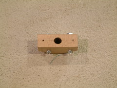
The key to waterproofing the ammo box is to exit all connections through one hole, then make sure the one hole is as waterproof as is pssible. To ensure this, I designed a waterproof wire stress releiving gromit. This gromit squeezes all of the wires together (six in all) along with the caulk, and is then screwed onto the lid of the ammo box. The pilot holes for the screws through the lid can be seen here.
37 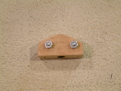
The nut that squeeze the wires laterally are seen here.
38 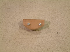
The heads of the machine screws are visible in this picture, the flat side is the side that contacts the lid of the ammo box and will be waterproofed with caulk, and double sided sticky door jamb sealer.
39 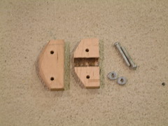
This is a view of the gromit dissasembled. The channel for the wires can be lrearly seen. The whole piece was made from one piece of 1" maple (for strength. Oak, walnut, or aluminum would also work.) I started by cutting out the shape from the wood, I then drilled out the center cavity using my drill press with a 3/8" forsner bit. Next, I drilled the nessescary holes for the machine screws, and cut the piece in half. Next, I bloted it back together and positioned it on the lid of the ammo box. Finally I drilled the pilot holes for the screw to attche it to the lid of th ammo box.
40 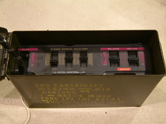
The circuit boards were small enough to fit in the ammo box along with the original sliders of the Karaoke machine. The sliders (from left to right) are: Microphone volume (does nothing, strictly a morale booster), Three band equalizer (next three sliders), balance, and volume control. The volume is left at about 3/4 volume. If more is needed, the box can be opened. A hole in the lower left will be the place that all of the wires are fed through.
41 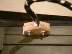
All five of the wires (LED power, battery power (routed through the toggle), left audio, right audio, and input) were shrink wrapped at the point that they would go through the gromit. The rest of the cable was wound to ensure that the wires would not stress too much. The imput, originally RCA left and right, was replaced with an 1/8" stereo jack (harvested from computer speakers, headphone cable would work as well)
42 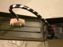
Enough slack was left in the box so that the entire lower potion could be detached from the lid. for adjustments. All of the cables attach to their original places behind the Karaoke machine slider face. The circuit boards are encased in foam in the ammo box to protect them from vibration and shock.
43 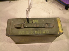
The cable was fed through the gromit, then clamped down and the whole gromit was attached to the inside of the lid. I this picture, the wires can be seen exiting the top of the ammo box. This is the only hole in the ammo box and extra attention was needed to make sure it was waterproof.
44 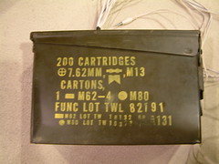
This is a view of the wires coming out of the top of the ammo box. As you can see, the exit point is slightly off center to the left. The ammo box will be cntered on the backpack below the center support. The wires (being off center) will miss the post and run along it's side.
45 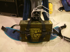 46
46 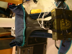
The wire's path can be better seen in this picture. The lateral supports for the ammo box have been added and the harness for the ammo box is now completed. There are two clips near the bottom of the straps that run up and down. These allow the box to be removed.
47 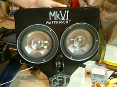
The faceplate has been painted with semi-gloss poyurethane and the logos have been stenciled on. all of the logo's are made with a silver sharpie. The top logo that reads "Mk.VI" means "Mark Six," it is the sixth back pack designed by GFI. This stencil was made by drawing the design that I wanted on a sticky not. Then cut out the negative areas and filled them in on the faceplate. "Waterproof," the next line down is self explanitory. This stencil was made by filling in the voids on one of those letter stencil things that comes with an art set. The lowest stencils read "Gueedo Fabrication Industries" in the first line. This was done freehand. "GFI" in the middle. This was done with a sticky note. The lowest line reads "mtnmck.pbwiki.com" this was done freehand as well. Seen also in this picture is the final layout for the speakers.
48 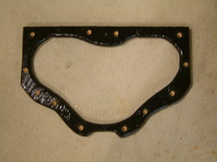
This is a picture of the gasket polyurethaned. Also, the pilot holes and countersinks have been drilled in preparation to seal it all up.
49 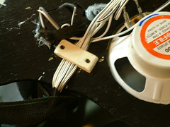
Here, a small clamp was made to ensure that the wires were held flat and organized as they passed under the gasket. There are only two holes in the back gasket. On for the six wires that lead from the ammo box, and one where the power wire passed under the gasket and reached the battery box. The clamp was made from a piece of 1/4" aspen that was filed down to size. These are then screwed to the back of the faceplate to clamp the wires to the faceplate.
50 
All of the wires to the audio are left slightly longer than needed because after the back is sealed. the speakers will be removed and sealed as well. Here, the wires are bunched up for slack.
51 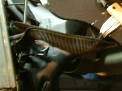
This is a picture of the protective cover for the wires. It was made from a piece of nylon strap and is designed to protect the wires from snapping if the box accidentally falls off of the harness, it will not tension the wires. This is because the strap is bolted onto the faceplate and the ammo box. The faceplate turned upside down is on the right of the picture. The ammo box is on the left, and the strap is in the center.
52 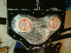
The faceplate is now completly sealed. A bead of caulk is placed on the back of the faceplate. Next, the plastic was cut to size and layed on that. Another bead of caulk was layered ontop of that. Finally, the gasket is screwed onto the faceplate sealing everything.
53 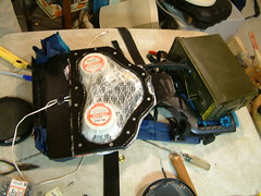
This is a view of all of the waterproofing complete. The faceplate and the Ammo Box are held togther with the nylon safety strap. Both the faceplate and the ammo box are upside down.
54 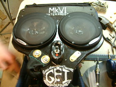
This is the Faceplate being prepared for attaching it to the backpack. The safety strap is attached with two bolts running through two gromits on the strap. The metal speaker covers were attached with three screws each. New holes had to be drilled in the covers in order for them to be better attached. The Brass plate on the right opposite from the safety strap gromits was made to cover up teo holes that were drilled for the strap's bolts originally. I cut the brass plate from a piece of thin guage brass. I cut the piece with aviation shears and rounded it with a file while holding the small poece in a jewelers ring clamp. I used metal letter stamps to punch in the words on the plate. The plate shows the backpack's serial number, owner, and mnufacturer.
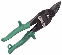
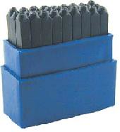
Jeweler's Ring Clamp, Aviation Shears, and Metal Letter Stamps
55 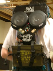
The First full test. The Backpack works flawlessly. Having all of the control on the portable audio player is not an inconvenience at all.
56 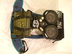
Here is the top view. The finish turned out well, and the whole thing fits together nicely. The facceplate screws through the fabric or the backpack in order to hold the straps on the backpack to the backpack itself.
57 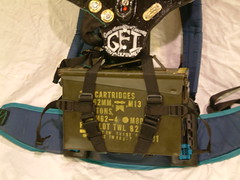
The lower half of the backpack completed
58 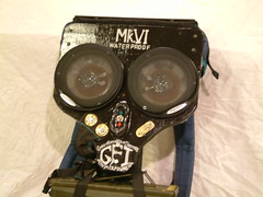
The upper half.
59 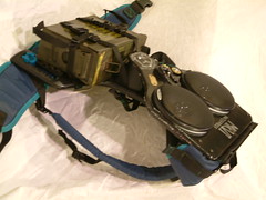
The side view of the backpack showing how slim the whole unit is. This was done to ensure that the center of gravity of the wearer was not altered too much. Wearing the other backpack that I had made was too heavy and bulky to be able to move around with it on.
60 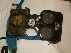
Finished Front
61 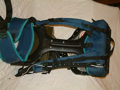
Finished back.
62 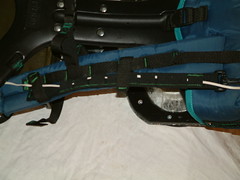
O the left strap. A piece of nylon strapping was added over the path through which the input cable runs ensures that the cable won't be ripped out when the back pack is picked up. This piece eliminates a major stress point on the wire.
63 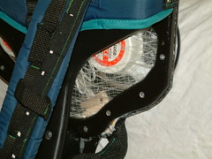
A closer view of 62. The white is the cable. The cable is held in place with small pieces of elastic sewn onto the nylon strap.
64 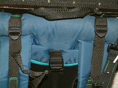
These straps were added onto the shoulder straps in order to pull the top of the backpack to the back of the wearer and were a very important additon in order to keep the pack from moving around as you dance ro your own music.
65 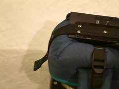
This is a close up of the strap that holds the homemade battery pack lid down. A piece of nylon is glued onto the top of the 1/4" Aspen lid that was painted black. The strap attaches with velcro which is screwed to the wooden post underneath.
66 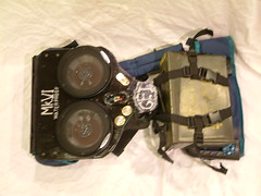
Top View.
67 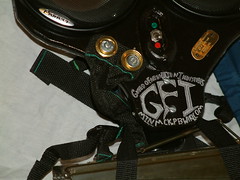
Close up of the gromits that hold the safety strap in place, and the switch and ownership/serial number plate.
68 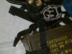
Close up at the logo.
69 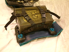
The bottom of the harness. The bottom most strap connects to the back pack at the left and the right of the sdjustment points. The bottom strap offers two more points of adjustment.
70 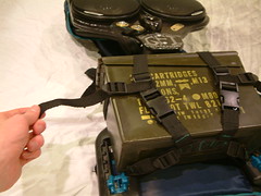
Showing how to sinch the box into a tighter position.
71 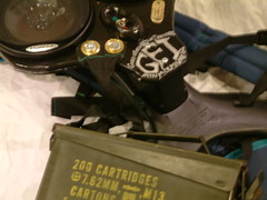 73
73 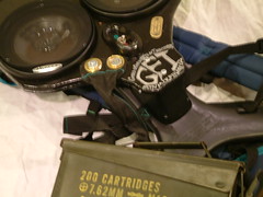
Detaching the ammo box for inspection. You can only pull it out so far until the safety strap holds it back.
72 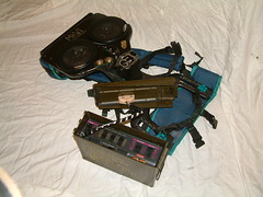
The lid of the ammo box now detaches and the slack of the wire now allows you to pull the box further out. to acsess the amplifier.
73 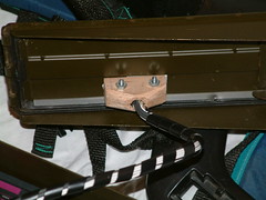
The waterproofing gromit completed.
74 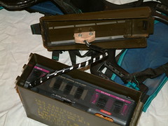
With the backpack layed out flat, the ammo box can sit upright.
75 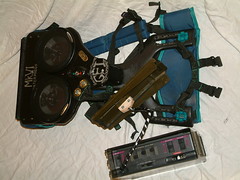
View of the backpack in dagnostic mode.
76 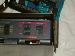
Close up of the Karaoke machine sliders. These connect to the smaller amplifier cicuit board. These are for balance and volume.
77 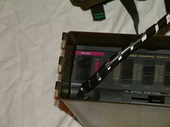
Close up of the wire exit hole. Also seen are the Echo slider (connected to nothing, serves as morale booster), three band equalizer (next three sliders), The pitch control on the bottom also does nothing.
78 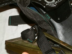
Close up of the large strap that connects the ammo box to the faceplate and contains all of the wires inside of it.
79 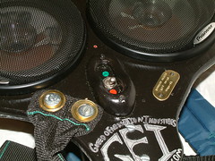
Faceplate front array.
80 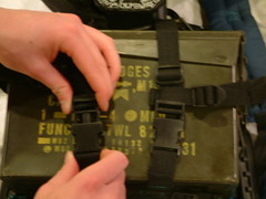
Re-ataching the ammo box.
81 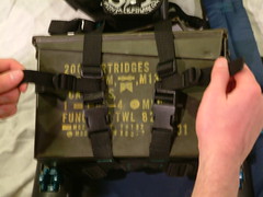
Final adjustment of the ammobox harness and the back pack is ready to rock.
82 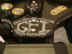
GFI
Comments (0)
You don't have permission to comment on this page.